This is exactly where construction lines come to the rescue. They´re not part of the final cut, they won´t be exported or machined, but they do make a big difference. They bring structure and clarity—and for those of us who use them regularly, they´re essential.
The Drawing Module: Everything You Need Without Leaving Lantek
One of the major advantages of Lantek Expert is that you don´t need an external CAD system. The built-in Drawing Module is powerful and self-sufficient. Inside the Home > Draw section, you´ll find 15 drawing tools, from simple two-point lines to regular polygons, arcs, rectangles, circles, oblongs—you name it.
Each tool includes a dropdown with extended options. But among them, one stands out as a true all-rounder: Construction Lines. For many experienced users, this tool is the Swiss Army knife of technical drawing in Lantek. Versatile, precise, and surprisingly efficient.
How I Start Every Drawing: Defining Boundaries with Construction Lines
Whenever I need to create or modify a part, the first thing I do is set boundaries using construction lines. Within the Construction Lines tool, the two options I rely on most are:
- Parallel
- Perpendicular
These help define the external limits of the part and pinpoint its geometric center. If I need to position features like holes, rectangles, or circles, I lay everything out using construction lines. This gives me full control before I start working on actual geometry.
And then come the curves. Here´s where I pay extra attention, especially when I´m working with DXF files from external sources. They can come with surprises.
One of the most common issues? Tangencies that aren´t actually tangent. Sometimes arcs are drawn roughly “by eye,” and even if the DXF looks okay, once you overlay construction lines, you realize something´s off. And if you don´t catch it in time, the manufactured part may end up with unwanted points or edges.
That´s when construction lines save the day:
Use them to verify curve behavior, detect poorly constructed tangents, and catch issues before they make it to the machine. Just because the DXF is “closed” doesn´t mean it´s correct.
Designing from Construction Lines: Smarter Geometry Starts Here
Here´s a little-known but incredibly useful feature in Lantek Expert: when you trim between two construction lines, those lines automatically become part of the real geometry.
Personally, I always start with a blank workspace and draw a horizontal and a vertical line intersecting at a known reference point. Then I:
- Create parallels, perpendiculars, bisectors, and midlines
- Save arcs and tangents for last
- And finally trim to generate the actual geometry
To anyone walking by, it might look like a screen full of noise—just lines in every direction. But to me, the part is already there, waiting to be cut from the excess. Like a hairdresser shaping a fresh style from a messy head of hair.
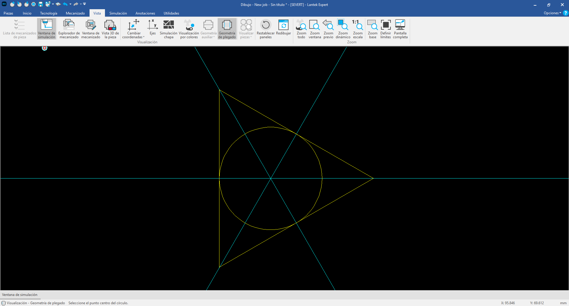
Real Example: Equilateral Triangle with an Inscribed Circle
Let´s go practical. Say you need to create an equilateral triangle with a perfectly centered inscribed circle. Here´s how to do it step-by-step using construction lines:
1. Draw the triangle
Use the Polygon tool and set it to 3 sides and the desired angle. That gives you your base shape.
2. Find the center
Draw a construction line from the top vertex to the midpoint of the opposite side. Then use the Midline (Bisector) tool for the other two sides. The intersection point is the exact center of the triangle.
3. Draw the circle
Use Circle by Radius or Circle by Center and Point, placing the center on the point you just found. Set the radius to fit neatly inside the triangle.
This is a simple example, but it illustrates the power of construction lines: precision, structure, and full control from the first click.
Less Chaos, More Control
Using construction lines isn´t just about keeping your drawing tidy. It´s a design strategy. It lets you identify potential issues early, build more accurate geometry, and work more efficiently.
Lantek Expert gives you the tools to go far beyond basic shapes. If you make construction lines part of your regular workflow, you´ll see real benefits—from faster setup to higher-quality parts.
So next time you open the Drawing Module, think of construction lines not as a helper, but as your precision toolkit. They´re not just guidelines—they´re the backbone of smarter design.
Catch you in the next edition of Sheet Happens. And remember: don´t let a single line get away from you.